From inside (document excerpt):
OWNER’S MANUAL AND PARTS LIST 36 ” Rotary Snow Thrower Article 311 SIMPLICITY MANUFACTURING COMPANY, The s “ow plow is shlppod (com the factorY in 2 “ado, “. The lar el’ o,,·ton oontains tho rotor hous_ it’g, skid .,I’MS, ddft cutlers. spout, “v ” bell for spoul, anti hot aIr doflector lor engIne. The smaller cartoH co “I,I ” ” llle drIve pulleys and bells, One “v ” pulley, “v ” bolt, push oor assembly, front lift rod, sp>ut adjuSting handlQ, support bracket. pIns and hair pIn cotlers. To assomble tho sno,,’ plOW, proceed in lhefollowing sequence: 1, Assemblo the pusl,oor assembly to tbe roar 01 the rotOr housing usIng 2 hex cap sCreWS 1/2 ” _ 13 x 2_1/2 ” 19.
Snow Blower and Snow Thrower User Manual Free Download. Snow Removal Operator’s Manual. Free Manual Download PDF.
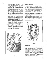
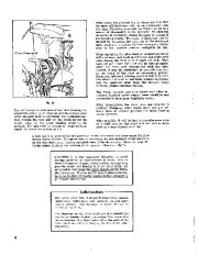
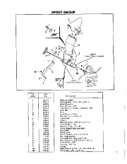
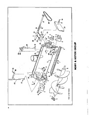
and 2 hex nuts 1/2_13 as shown In llgure 1. H.x Cop Screw, Loci< N " 3. Assemble the drill cUlt rs. in plaoe "o eath sido 01 tM rotor hOlleiLlgas' ;;llOwi>.in!igure 3, Cop ” ” ” ” “,_ Lckwo,h. ” Hax Nut, · Ddft Cu.ter Rotor Hou’ing 4. Awlya coating of light oil to the ” “ok of !he di.charge .pout mOUllting collar, and in.tall the .poul #1, Fig. 4, in plnee on the rotor housi g as shown. The application of oil is necessary to prevent rust and to allow the spout to mtate freely. Fig. 4, to thc rotor housing, sing two W’-20 x 5/8 ” 19. hex capscrews, ‘,f’ lClCkw hers, and W’-20 hex nuts. Tighten securely. “, Atlach the spout control rod hearing #2, Insert the e d of the “Spout control rod #3, Fig. 4, Ibrough the bearing and s “ecure with 2. Assemble the skid shoes to each sl _ Wa>h “,,Lckwa.h. ” – Hox Nul> HOU “; “‘ ::- ” , CORD CLAMP CORD. SPOUT DRIVE’–l TUB( delve shaft, the tube or post ia angled or inclined toward the center of the l,low .nd not tow.rd the end of the plow. Install the thin washer and the woodruff key to rotor drive shaft. Mounl lhe pulley flush again5l the washer with hub of pulley 10 face out or away from pUlley post assembly. Tighten 5et screw and lock pulley in plaoe. See figure 6. Pl.ce “v ” hell “N· In position On upper pulley and insert the stud 01 the drive group into the pUlley post .ssembly. The s od must be aligned 50 thai the 2 key (one key on each side of stud) are inserted into the ,Iota on the pulley post. Screw adjusting nut “Y ” upwards on the stu until the “v ” belt may be placed Over the pulley on the rolor drive shaft as shown in Iiguro 7. Screw thia nut dOwnward against the spring on the stod until II oompresees the st>rin io “- height of 2 “, This will tension the “v ” belt properly. lnoreaslng the tension 01 “v ” bell will only “au e premature belt failure I COllIlect tho drive group to tho rotor drive shalt in Ihe following mannor: Two washers are “hipped loose In the smal_ ler cartllIl; one washer Is thielmr than the other and haa “- larger hole or bore tb= tho lhin waahor. Assemble the thick washer.
Wikipedia’s page for Simplicity Outdoor
Publisher: www.simplicitymfg.com


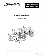 Simplicity 311 36-Inch-Snow Blower Owners Parts Manual - 1 of 12
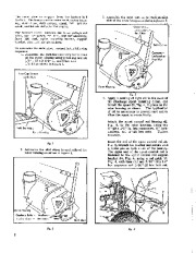 Simplicity 311 36-Inch-Snow Blower Owners Parts Manual - 2 of 12
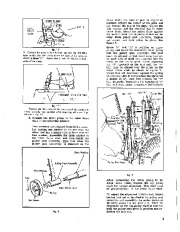 Simplicity 311 36-Inch-Snow Blower Owners Parts Manual - 3 of 12
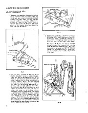 Simplicity 311 36-Inch-Snow Blower Owners Parts Manual - 4 of 12
 Simplicity 311 36-Inch-Snow Blower Owners Parts Manual - 5 of 12
 Simplicity 311 36-Inch-Snow Blower Owners Parts Manual - 6 of 12
 Simplicity 311 36-Inch-Snow Blower Owners Parts Manual - 7 of 12
 Simplicity 311 36-Inch-Snow Blower Owners Parts Manual - 8 of 12
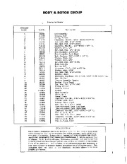 Simplicity 311 36-Inch-Snow Blower Owners Parts Manual - 9 of 12
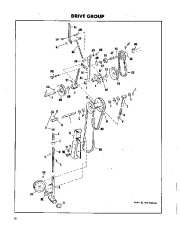 Simplicity 311 36-Inch-Snow Blower Owners Parts Manual - 10 of 12