From inside (document excerpt):
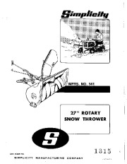
MFRS. NO. 561 27 ” ROTARY SNOW THROWER SER. cORM-P5G l;) 13 -, MANUFACTURING COMPANY SIMPLICITY SPOUT ASSEMBLY ROTOR BODY SKID HITCH ASSEMBLY SHOES 4 Figure 1. PACKING ASSEMBLY The 27 ” Rotary Snow Thrower is delivered complele in one oarton. The carton contains: 1· Hitch As,embly 1. Lift Rod Assembly 1 – Spout Control Rod 1 – Spout Tube and Cable Assembly 1. Spout Control Rod Support Assembly 2 – Skid Shoes I· Spout Assembly 1· Body and Rotor Assembly 1 – Bag of Hardware 1 – Drive Belt I.
Snow Blower and Snow Thrower User Manual Free Download. Snow Removal Operator’s Manual. Free Manual Download PDF.
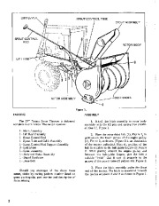
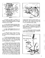
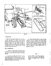
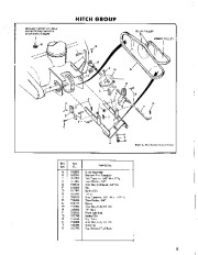
Attaoh the hitoh assembly to rotor body assembly with the (2) pins and spr(ng clips provided. See (1). Figure 1. 2. Place the rotor drive belt (1), Figure 2, in position on the lower groove of the engine pulley (2). Figure 2, as shown. (Figure 2 is an illustration of the tractor underside). Note the position of the helt in relation to the belt-guide fingers (3). Figure 2. After passing around the engine pulley and between the beit-guide fingers, give the belt a suitable “twist ” that it m.y fit properly to the groove of the power take-off pulleys (4), Figure 2. 3. Place the hitch assembly under the front end of the tractor. The hitch is SU.’lpended beneath the tractor at points 2 and 3 as shown in Figure 1. Should any shortages of the above items occur, advise by stating paekers number listed on green packing slip, part number and description of items missing. 2 Figure 2. Figure 3. rod guide support and secure with the clamp, liner and 5/16 “-lB x 1-1/4 ” oapscrew and 5/16 “·18 lock nut. Tighten securely to permit spout control rod to be turned with slight pressure applied. 10. Connect one end of the 11ft rod (8), Figure I, to tbe lift bracket on the rotor housing, using a spring clip. The other end of the lift rod is connected to the lift lever on the tractor and is seoured with a spring clip. 4. Pull the rotor drive belt to bring aU slack forward on the left side of the tractor as shown at 1, Figure 3. Install tbe slack end of the belt in place around the rotor drive pulley. 5_ Attaoh the skid shoes to the body .embly using the 3/8 “·16 x 3/4 ” carriage bolts, 3/8 ” plain washer, 3/8 ” lockwasher and 3/8 “-16 full hex nuts as$hown at (4), Figure 1. 6. Apply. light coating of oil to the ne ‘,oN ””H nn.I 81£ ””I’ “M ‘0’1
Wikipedia’s page for Simplicity Outdoor
Publisher: www.simplicitymfg.com


 Simplicity 561 27-Inch Rotary Snow Blower Owners Manual - 1 of 12
 Simplicity 561 27-Inch Rotary Snow Blower Owners Manual - 2 of 12
 Simplicity 561 27-Inch Rotary Snow Blower Owners Manual - 3 of 12
 Simplicity 561 27-Inch Rotary Snow Blower Owners Manual - 4 of 12
 Simplicity 561 27-Inch Rotary Snow Blower Owners Manual - 5 of 12
 Simplicity 561 27-Inch Rotary Snow Blower Owners Manual - 6 of 12
 Simplicity 561 27-Inch Rotary Snow Blower Owners Manual - 7 of 12
 Simplicity 561 27-Inch Rotary Snow Blower Owners Manual - 8 of 12
 Simplicity 561 27-Inch Rotary Snow Blower Owners Manual - 9 of 12
 Simplicity 561 27-Inch Rotary Snow Blower Owners Manual - 10 of 12