From inside (document excerpt):
STIHL FH7S Instruction Manual Owner’s Manual Assembling Safety Precautions Operating Instructions Maintenance I @ Adjusting the Carburator Units with Idle Speed Adjusting Screw LD Adjusting idle speed · On trimmer and power edger: Mounting the cutting tool On power scythe and hedge trimmer: Check cutting blades clean if necessary (blades must be clean, move freely and not be bent or warped) · · Check the air filter and clean it if necessary. Check spark arresting screen in muffler and clean or replace as necessary.
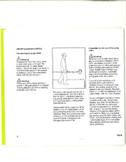
Engine stops while idling: Turn the idle speed screw (LD) clockwise until engine runs smoothly the cutting tool must not rotate. Note: This supplement replaces the chapter “Adjusting the Carburetor ” in the owner manuals for Fe 75, FH 75, FS 75 and HL 75 Cutting head runs when engine is idling: Turn the idle speed screw (LD) counterclockwise until cutting tool stops running and then turn the screw about another one full turn in the same direction (counterclockwise). · Motor Management Exhaust emissions are controlled by the design of the fundamental engine parameters and components (e.g. carburation, ignition, timing and valve or port timing) without the addition of any major hardware. Carefully screw the idle speed screw (LD) counterclockwise (lel1hand thread) down onto its seat. Then open it two full turns clockwise (standard setting). · Start the engine and warl “‘1 it up. Adjust idle correctly with the idle speed screw (LD): The cutting tool must not rotate. The carburetor is tuned at the factory for an optimum fuel-air mixture under all operating conditions. FC 75, FH 75, FS 75, HL 75 Contents Parts and Controls Definitions Safety Precautions Storing the Machine Assembling the Unit Fuel Mix Fueling Adjusting Cutter Bar Angle Fitting the Harness Starting Applications Cleaning the Air Filter Motor Management Carburetor Adjustment Checking the Spark Plug Spark Arresting Screen in Muffler LUbricating Gearbox LUbricating the Drive Shaft Replacing the Starter Rope and Rewind Spring Sharpening Instructions Maintenance Chart Specifications Operating Instructions Andreas Stihl AG & Co. Limited Warranty Federal Emission Control Systems Utility Engines 20 20 This manual contains warnings, operating and safety precautions for the STIHL FH 75 scrub cutter. Pay special attention to the safety precautions outlined on pages 4 to 10. Allow only persons who understand this manual to operate your scrub cutter. To receive maximum performance and satisfaction from your STIHL scrub cutter, it is important that you read and understand the maintenance and safety precautions before using your scrub cutter. Contact your STIHL dealer or the STIHL distributor for your area if you do not understand any of the instructions in this manual. ‘&warningl Because a scrub cutter is a high-speed, gasoline-powerd cutting tool, some special safety precautions must be ubserved to reduce the risk of personal injury. Careless or improper use may cause serious or even fatal injury. STIHL’s philosophy is to continually improve all of its products. As a result, engineering changes and improvements are made from time to time. If the operating characteristics or the appearance of your scrub cutter differ from those described in this manual, please contact your STIHL dealer for information and assistance. Printed on chlorine-free paper 1998 Andreas Stihl, Waiblingen 04582253021 M 5.S9 PM Printed in USA FH75 1 Parts and Controls Loop handle Barrier bar Carrying loop Slide control Throttle trigger interlock Throttle trigger Spark plug boot Air filter cover 9 Machine support Cutting blade Cutting blade scabbard Blade drive gear Quadrant Angle drive Adjusting lever Sliding sleeve Drive tube Fuel tank Fuel filler cap Starter grip Fuel pump Choke lever Carburetor adjusting screws Muffler 9 11 o 0 15 0 H75 Definitions 1. Loop handle For easy control of machine during cutting work. 10. Cutter blade Steel blades for cutting scrub and shrubs. 18. Fuel tank For fuel and oil mixture. 19. Fuel filler cap 2. Barrier bar Helps keep unit at a safe distance from operator’s feet and legs. 11. Cutter blade scabbard Covers cutter blade when scrub cutter is not in use. For closing the fuel tank. 20. Starter grip The grip of the pull starter, which is the device to start the engine. 3. Carrying loop The device to connect the scrub cutter to the harness. 12. Blade drive gear Converts rotary motion of angle drive into reciprocating movement of cutter blades 21. Fuel pump Provides additional fuel feed for a cold start. 4. Slide control Starting throttle lock and stop switch. Keeps the throttle partially open during starting and switches the engine’s ignition off and stops the engine. 13. Quadrant Locks the cutter blades in the required position 22. Choke lever Eases engine starting by enriching mixture. 14. Angle drive Transmits rotary motion of drive shaft to the blade drive gear 23. Carburetor adjusting strews For tuning carburetor 5. Throttle trigger interlock Must be depressed before the throttle trigger can be activated 15. Adjusting lever Lever for swiveling cutter blades to required angle 24. Muffler Attenuates exhaust noises and diverts exhaust gases away from operator. 6. Throttle trigger Controls the speed of the engine. 16. Sliding sleeve Sleeve for locking and unlocking the adjusting mechanism 7. Spark plug boot Connects the spark plug to the ignition wire. 17. Drive tube Device to connect the engine with the gearbox. 8. Air filter cover Covers the air filter element. 9. Machine support For resting machine on the ground. FH75 3 ‘. Safety Precautions & Warning! Because a scrub cutter is , a high-speed, fast-cutting


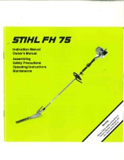 STIHL Owners Manual - 1 of 30
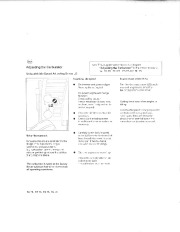 STIHL Owners Manual - 2 of 30
 STIHL Owners Manual - 3 of 30
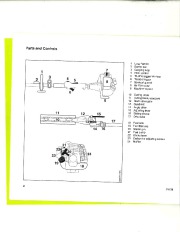 STIHL Owners Manual - 4 of 30
 STIHL Owners Manual - 5 of 30
 STIHL Owners Manual - 6 of 30
 STIHL Owners Manual - 7 of 30
 STIHL Owners Manual - 8 of 30
 STIHL Owners Manual - 9 of 30
 STIHL Owners Manual - 10 of 30