From inside (document excerpt):
Commercial Products Hydroject 3000/4000 ® Troubleshooting Guide PART NO.97928SL, Rev. A This page is intentionally blank. TORO ® Hydroject® 3000/4000 Table of Contents Troubleshooting 1 Product Overview 2 Components 6 Water System Operation 48 Water System Testing 58 Unit Storage .78 Maintenance Chart 80 Use of This Manual The information contained in this manual is supplementary to material found in other sources, it is not a replacement for them.
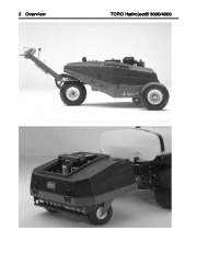
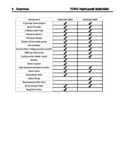
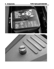
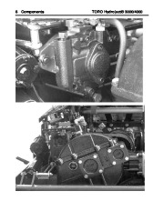
You should always consult Service Manuals, Service Bulletins, Operator’s Manuals and Parts Books when necessary. Service Manual Updates and Service Bulletins can be found on the internet at: www.toro.com/golf/custsvc.html This Manual and the training program, which it supports, are both designed to help you gain knowledge of the product, and to inform you of when and why to make the necessary repairs. We have also included tips for performing those repairs. This program is designed for you. Your input and participation is appreciated. There is plenty of space in this manual for you to add your own notes and observations 2 Overview TORO Hydroject® 3000/4000 TORO Hydroject® 3000/4000 The Hydroject® is a patented machine that aerates the ground with “water jets “. These jets are pulses of high velocity water, released at regular intervals. Overview 3 For this machine to operate properly, the owner or operator should understand the individual components and their relationship to the complete system. The Hydroject® 3000 is a hydrostatic driven walk aerator. The unit needs to be connected to a clean water supply to aerate. The Hydroject® 4000 is a pull behind aerator. The higher transport speeds make the 4000 suitable for tees and problem areas on the fairway. The Hydroject® 4000 usually gets its water from a tank on the towing vehicle. NOTES 4 Overview TORO Hydroject® 3000/4000 Comparison 2 cylinder Onan Engine Quick Coupler 5 Micron inlet Filter Pressure Switch Pressure Gauge Engine driven water pump Accumulator Accumulator charge pressure switch 5000 psi relief valve Cycling valve (water valve) Rollers Roller washer High pressure aeration nozzles Drain valve Hydrostatic drive Boost Pump Boost pump relief valve 25 micron pre-filter Regulator Valve Hydroject 3000 Hydroject 4000 TORO Hydroject® 3000/4000 Overview 5 The Hydroject® 3000/4000 aerators use most of the same components in the water injection system. While there are differences in the machine drive, the main water injection system is the same. The chart on the previous page shows the similarities and differences between the two units. NOTES 6 Components TORO Hydroject® 3000/4000 TORO Hydroject® 3000/4000 Engine Components 7 The Hydroject® is powered by an Onan, 24 HP, air cooled, twin cylinder, electric start, gas engine. The engine is equipped with solid state ignition, and powers the water pump, water valve, and on the 3000, the hydrostatic transmission. The engine uses 3 quarts of 30-weight engine oil and the oil should be changed every 100 hours, after the initial 25-hour change. Oil Filter PN. 57-8530 The air filter should be serviced every 100 hrs, and the filter element replaced every 200 hrs. Air Filter foam pre-cleaner PN 82-0670. Air Filter element PN. 82-0670. During aeration, operate the Hydroject® at full engine RPM. Proper engine idle speeds. Low idle 1500 – 1800 RPM. High Idle 3500 ± 50 RPM. Fuel The fuel tank holds 10 gallons of regular unleaded gasoline (9 gallons on the Hydroject® 4000) and should operate the unit for approximately 4 hours. There is a fuel shut off valve located below the fuel tank and this valve should be closed during periods of non-use. NOTE: Take care in filling any fuel tank, and fill the tank to 1 inch below the top of the tank. Always wipe up any spilled fuel to prevent a fire hazard. The Fuel Filter should be replaced every 200 hrs. Fuel Filter PN. 71-5960. NOTES 8 Components TORO Hydroject® 3000/4000 TORO Hydroject® 3000/4000 Hydrostatic Pump (3000 Hydroject® Only) Components 9 The Sundstrand, series 70 hydrostatic pump, is belt driven and provides variable oil flow to operate the traction wheel motor, the traction bail, located on the tiller handle, is connected to the swash plate in the hydrostatic pump and provides speed and directional control. The unit aerates in both directions. NOTE: There is a bypass valve located on top of the hydrostatic pump, this valve provides for limited movement of the unit with the engine off. Cam Gear Box The cam gearbox operates the cycling valve and also serves as the hydrostatic oil reservoir, on the Hydroject® 3000. The hydrostatic transmission uses 5 quarts of DTE 26. NOTE: The oil level can be checked through the sight glass on the side of the reservoir. NOTES 10 Components TORO Hydroject® 3000/4000 TORO Hydroject® 3000/4000 Transmission Filter (3000 Hydroject® Only)
Wikipedia’s page for Toro Company
Company Web Site: www.toro.com


 Toro Commercial Products Hydroject 3000 4000 Troubleshooting Guide 97928SL Rev A - 1 of 84
 Toro Commercial Products Hydroject 3000 4000 Troubleshooting Guide 97928SL Rev A - 2 of 84
 Toro Commercial Products Hydroject 3000 4000 Troubleshooting Guide 97928SL Rev A - 3 of 84
 Toro Commercial Products Hydroject 3000 4000 Troubleshooting Guide 97928SL Rev A - 4 of 84
 Toro Commercial Products Hydroject 3000 4000 Troubleshooting Guide 97928SL Rev A - 5 of 84
 Toro Commercial Products Hydroject 3000 4000 Troubleshooting Guide 97928SL Rev A - 6 of 84
 Toro Commercial Products Hydroject 3000 4000 Troubleshooting Guide 97928SL Rev A - 7 of 84
 Toro Commercial Products Hydroject 3000 4000 Troubleshooting Guide 97928SL Rev A - 8 of 84
 Toro Commercial Products Hydroject 3000 4000 Troubleshooting Guide 97928SL Rev A - 9 of 84
 Toro Commercial Products Hydroject 3000 4000 Troubleshooting Guide 97928SL Rev A - 10 of 84