From inside (document excerpt):
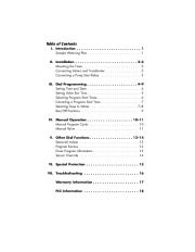
Model 53603 Owner’s Manual Español – P. 19 Français – P. 39 Table of Contents I. Introduction 1 Sample Watering Plan 1 II. Installation Mounting the Timer Connecting Valves and Transformer . Connecting a Pump Start Relay . . . 23 2 2 3 III. Dial Programming 49 Setting Time and Date 4 Setting Valve Run Time 5 Selecting Program Start Times . 6 Canceling a Program Start Time 7 Selecting Days to Water .
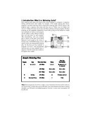
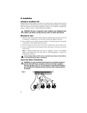
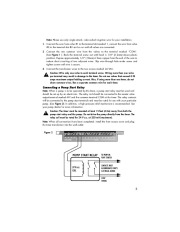
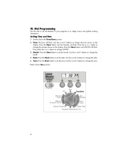
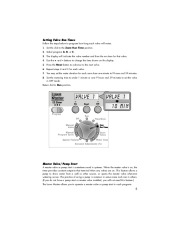
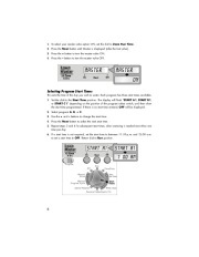
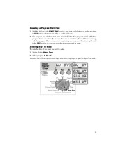
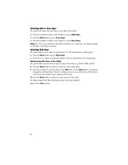
78 Run/Off Positions . 9 IV. Manual Operation 1011 Manual Program Cycle . 10 Manual Valve . 11 V. Other Dial Functions Seasonal Adjust . Program Review . Erase Program Information Sensor Override . . . . 1214 . 12 . 13 . 13 . 14 VI. Special Protection . 15 VII. Troubleshooting 16 Warranty Information 17 FCC Information 18 I. Introduction: What is a Watering Cycle? Each watering cycle opens and closes all the valves assigned to a program, in sequence, starting with the lowest valve number. For example, in the sample watering plan shown, program A has three start times which initiate three watering cycles. All four valves in the program water in sequence, three times each day, once at 7:00am, once at 5:00pm, and once at 11:00pm. This timer can be set to start three watering cycles per program. The three programs are all completely independent of each other, giving you the freedom to include any combination of valves in each program and the ability to select different watering days and start times for each program. After programming, write your watering plan in pencil on the back of the Quick Reference Card, located on the inside of the timer door. The REVIEW feature can be used to review your programmed watering plan. For the days you have selected in programs A, B and C, each programmed start time turns on every selected valve in sequence, from the lowest valve number to the highest valve number. Sample Watering Plan Program A Days Su, Tu, Th, Fr Water Start Times (#1) 7:00am (#2) 5:00pm (#3) 11:00pm B C Odd Days Once every 10 days (#1) 5:00am (#1) 4:00am Valves 1, 2, 3, 5 Same as above Same as above 5,6 4 Valve Run Time Duration 10 minutes (1, 3, 5) 15 minutes (2) Same as above Same as above 10 minutes each (5,6) 1 Hour Note: Each program (A, B and C) is simply a set of instructions that direct which valves to run for how long, on which days and at what time. If you need numerous start times or several schedules, you will need to use multiple programs. However, in some cases one program will be sufficient. 1 II. Installation Selecting an Installation Site Install the timer with the display at eye level. If you will be using a pump, the timer must be mounted at least 15 feet (4.5m) away from your pump start relay and pump. Do not plug the timer into any power circuit serving a refrigerator, a pump, an air conditioner, a garage door opener, a washer or dryer, or other high-powered equipment. WARNING: This timer is designed for indoor installation only. Installing this timer outdoors will void the warranty and may result in an electric shock hazard. Mounting the timer 1. Select an indoor location within 6 feet (1.8m) of an outlet to mount your timer. Do not use an outlet that is controlled by an On/Of switch. Mount with display at eye level. 2. Drive one #8 screw into wall leaving approximately 1/8 ” (3.2mm) exposed. Use a plastic anchor sleeve if wall is plaster board or masonry. 3. Mount the hanger kit to the top/back of the timer. Hang the timer on the mounting screw. 4. Drive two additional #8 screws through the holes at the bottom of the timer case into the wall to secure. Note: To enable programming the timer prior to installation, connect a 9-volt Alkaline battery to the battery clip at this time. Refer to “Dial Programming ” on page 4 for programming instructions. Caution: Replace battery with the same or equivalent type. Dispose of used batteries as recommended by the battery manufacturer. Connect the Valves & Transformer WARNING: To avoid an electrical shock hazard, do not plug the transformer into the outlet until all wire connections to the timer have been completed. The timer operates on 24 V a.c. Do not attempt to connect the timer directly to the wall outlet. This will destroy the timer and may result in electrical shock or fire hazard. Figure 1 2 Note: Please use only single strand, color-coded irrigation wire for your installation. 1. Connect the wire from valve #1 to the terminal slot marked 1, connect the wire from valve #2 to the terminal slot #2 and so on until all valves are connected. 2. Connect the one common wire from the valves to the terminal marked “COM “. (See Figure 1 ). Back the terminal screw out until head is 1/8 ” (3.2mm) above plastic partition. Expose approximately 1/2 ” (13mm) of bare copper from the end of the wire to reduce short circuiting of two adjacent wires. Slip wire through hole under screw and tighten screw until wire is secure. 3. Connect the transformer wires to the two screws marked 24 VAC. Caution: Wire only one valve to each terminal screw. Wiring more than one valve per terminal may result in damage to the timer. Do not use valves that exceed 0.25 amps maximum output holding current. Also, if using more than one timer, do not share common wires. Run a separate common wire for each timer. Connecting a Pump Start Relay Note: When a pump is to be operated by the timer, a pump start relay must be used and should be set up by an electrician. The relay coil should be connected to the master valve output terminal marked MV and the common terminal COM at the timer. The relay contacts will be connected to the pump start terminals and must be rated for use with your particular pump. (See Figure 2). In addition, a high pressure relief mechanism is recommended. See your pump dealer for more information. Caution: The timer must be mounted at least 15 feet (4.5m) away from both the pump start relay and the pump. Do not drive the pump directly from the timer. The relay coil must be rated for 24 V a.c. at 250 mA (maximum). Note: When all connections have been completed, install the front access cover and plug the timer transformer into the wall outlet. Figure 2 V a.c. 3 III. Dial Programming Use the dial to set all elements of your program or to simply review and update existing information. Setting Time and Date 1. Set the dial to the Time/Date position. 2. Time: The hour will flash. Use the + and buttons to change the hour shown on the display. Press the Next button and the Minutes will flash. Press the + or button to change the minutes shown on the display. Press the Next button and AM/PM will flash. Press either the + or button to change AM/PM. 3. Month: Press the Next button to set the month. Use the + and buttons to change the month. 4. Date: Press the Next button to set the date. Use the + and buttons to change the date. 5. Year: Press the Next button to set the year. Use the + and buttons to change the year. Return dial to Run position. 4 Setting Valve Run Times Follow the steps below to program how long each valve will water. 1. Set the dial to the Zone Run Time position. 2. Select program A, B, or C. 3. The display will indicate the valve number and then the run time for that valve. 4. Use the + and buttons to change the time shown on the display. 5. Press the Next button to advance to the next valve. 6. Repeat steps 4 and 5 for each valve. 7. You may set the water duration for each zone from one minute to 9 hours and 59 minutes. 8. Set the watering time to under 1 minute or over 9 hours and 59 minutes to set the valve in OFF mode. Return dial to Run position. Master Valve/Pump Start A master valve or pump start is sometimes used in systems. When the master valve is on, the timer provides constant output to that terminal when any valves are on. This feature allows a pump to draw water from a well or other source, or opens the master valve whenever watering occurs. The practice of using a pump is common in some areas and rare in others. (If you do not have a pump start or master valve installed, you will not need this feature.) The Lawn Master allows you to operate a master valve or pump start in each program. 5 1. To select your master valve option ON, set the dial to Zone Run Time. 2. Press the Next button until Master is displayed (after the last valve). 3. Press the + button to turn the master valve ON. 4. Press the button to turn the master valve OFF. Selecting Program Start Times This sets the time of the day you wish to water. Each program has three start times available. 1. Set the dial to the Start Time position. The display will flash “START A1, START B1, or START C1 ” depending on the position of the program select switch, and then show the start time programmed. If there is no start time entered, OFF will be displayed. 2. Select program A, B, or C. 3. Use the + and buttons to change the start time. 4. Press the Next button to select the next start time. 5. Repeat steps 3 and 4 for subsequent start times, when watering is needed more than one time per day.


 Toro Owners Manual - 1 of 20
 Toro Owners Manual - 2 of 20
 Toro Owners Manual - 3 of 20
 Toro Owners Manual - 4 of 20
 Toro Owners Manual - 5 of 20
 Toro Owners Manual - 6 of 20
 Toro Owners Manual - 7 of 20
 Toro Owners Manual - 8 of 20
 Toro Owners Manual - 9 of 20
 Toro Owners Manual - 10 of 20