From inside (document excerpt):
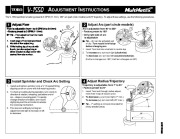
ADJUSTMENT INSTRUCTIONS 1 Adjust Flow Flow is adjustable from 1 to 9 GPM (4 to 34 l/mn) · Factory preset to 3 GPM (11 l/mn) Tip Flow adjustment can be made wet or dry. 1. Insert edge of Toro tool (provided) into slot of flow adjust ring. 2. While holding top of nozzle with thumb, turn flow adjust ring in either direction to align arrow with desired flow rate number. + TM The V-1550 sprinkler is factory preset to 3 GPM (11 l/mn), 180° arc (part circle models) and 25° trajectory.
Lawn Sprinkler User Manual Free Download. Irrigation Free Instruction Manual Download PDF.
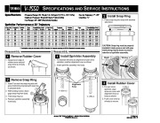
To adjust these settings, use the following procedures. 2 2 Adjust Arc (part circle models) To decrease arc: turn tool left (counterclockwise). (Full turn changes arc 180°; Half turn changes arc 90°) 3 Install Sprinkler and Check Arc Setting 1. Install and tighten sprinkler onto a 3/4 ” threaded fitting aligning arrow on cover with left watering border. 2. To check arc setting during operation, turn nozzle in direction of rotation, releasing just before end of arc observe reversing point. To quickly change direction of rotation, turn nozzle slightly beyond the arc border to actuate the reversing mechanism. 3. Fine tune arc setting by turning arc adjustment slot right to increase or left to decrease. 4 Adjust Radius/Trajectory 1. Insert Toro tool through radius adjustment hole in top of nozzle cover. 2. To decrease (), turn tool right (7° min.). To increase (+), turn tool left (25° max.). Tip 7° setting is not recommended for newly seeded areas. Optimum Pressure: 50 psi (3.5 kg/cm2) (344.8 kPa) · Arc Range: 40°360° (Part Circle Models) · Nozzle Trajectory: 7°25° · Inlet Size: 3/4 ” 2 Install Snap Ring 1. Place snap ring into body with beveled side down. Sprinkler Performance at 25° Trajectory Flow Adj. Pressure Precipitation rates are calculated at 55% of diameter for triangular spacing and 50% of diameter for square spacing. Disassembly Reassembly CAUTION: Snap ring must be properly installed in body groove and with gray interlocking ring as shown to ensure retention of sprinkler assembly. 1 Remove Rubber Cover 1. Grasp lower edge of rubber cover and pull away from lip of body as shown. 1 Install Sprinkler Assembly 1. To maintain left side arc alignment of part circle sprinkler, position alignment keys as shown. 2. Insert sprinkler assembly into body. Right Wrong 2 Remove Snap Ring 1. Insert Toro tool into snap ring slot until gray interlocking ring beneath snap ring is pressed down. 2. With twisting motion, disengage snap ring from body. 3. Twist snap ring out. 4. Remove sprinkler assembly from body. Alignment Keys V-1550-12 3 Install Rubber Cover 1. For part circle sprinkler, align arrow on cover with alignment keys on body as shown. 2. Push cover onto lip of body to secure.


 Toro Owners Manual - 1 of 2
 Toro Owners Manual - 2 of 2