From inside (document excerpt):
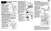
ENGLISH Toro RainSensorTM Model TRS Detailed Installation Instructions Rainfall Adjustment (Figure 2) The RainSensor can be adjusted to respond when it has detected nominal rainfall in the following amounts: 3mm, 6mm, 13mm or 19mm. Carefully rotate the Rainfall Adjustment Cap so the pins are positioned in the desired slots. Be sure to align the slots and pins properly, as this adjustment does not require excessive force.
Lawn Sprinkler User Manual Free Download. Irrigation Free Instruction Manual Download PDF.
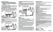
Figure 2 User’s Guide Introduction Congratulations on your purchase of the Toro RainSensor. The RainSensor is designed for easy installation, so your sensorcontrolled irrigation system will be up and running in minutes. Before attempting to install the RainSensor, please read through these instructions in their entirety, and refer to the instructions provided with your irrigation system controller/timer regarding the connection and use of a rain sensor or rain switch. The RainSensor is designed to work with either Normally Open or Normally Closed sensor circuits. Important: Please note the following information regarding installation and use of the RainSensor. · The RainSensor is designed to operate with 24 Vac power only. Connecting the sensor control wiring to 120/240 Vac power may result in severe equipment damage. · Installation methods must comply with all applicable national and local building codes. If you are unsure about proper wiring practices, have a qualified contractor perform the installation for you. · The RainSensor unit should never be submerged in water or installed inside a rain gutter. Mounting the RainSensor Select a mounting location for the RainSensor as close to the controller as possible. If the 7.5m connection cable will not reach the controller, it can be extended up to 30.5m using 1 mm2 outdoor-rated wire. The RainSensor location must be away from sprinkler spray, exposed to unobstructed rainfall and have similar sun exposure as the landscape being watered. A rain gutter is an ideal location for the RainSensor. Simply position the bracket with the thumbscrew under the gutter lip and tighten to secure (do not over-tighten). See Figure 4. The RainSensor can also be mounted on any suitable solid structure such as the pitched edge of the roof, a shed or fence using the two supplied stainless steel screws. See Figure 5. Once fastened securely, adjust the RainSensor on the mounting bracket as needed to align the housing vertically. Figure 4 Changing the RainSensor Configuration The RainSensor is configured for Figure 3 Normally Closed sensor circuit Normally Closed operation. If your controller requires a Normally Open type sensor, reconfigure the RainSensor control switch as follows: 1. Refer to Figure 3. Unscrew the bottom cover. Carefully slide the switch board assembly out. Normally Open 2. Carefully pull the wire connector from the left tab of the switch and attach it to the center tab. Leave the right wire connected. 3. Reassemble the RainSensor making sure the switch board is properly inserted. Do not over-tighten thumbscrew To Controller Rain gutter (cross section view) Figure 5 RainSensor Components (Figure 1) 1- Spindle – Press down to manually test sensor operation. 2- Rainfall Adjustment Cap Figure 1 Enables sensor to be easily adjusted for detection of rainfall 3 from 3mm to 19mm. 3- Universal Mounting Bracket 4 with Quick-ClipTM – Simplifies installation on rain gutter or roof eaves/fascia. RainSensor adjusts easily to the vertical position. 4- 7,5 m control wire provided. 1 To Controller 2 Stainless Steel Screws Routing the Control Wire After mounting the RainSensor in a suitable location, carefully route the sensor wire back to the controller. Avoid routing the wire over sharp edges where abrasion may occur. For best results, hide the wire where possible by it tucking it under shingles and/or moldings. Seal any holes made by passing the wire through structures. 1 Connecting the Control Wire Caution: Do not connect the RainSensor directly to 120/240 V ac power as this may result in irreversible damage. If you are in doubt, contact a qualified installer or electrician. 1. Disconnect power to the controller. 2. Review the following connection diagrams in Figures 6, 7 and 8. Follow the applicable instructions provided in steps A or B or C. A. Controllers with sensor terminals: Refer to Figure 6. Find the controller sensor terminals (generally marked “Sensor “, “SEN ” or “S “) and directly connect the control wires to these terminals in any order. There may be a jumper tab or wire between the sensor terminals that must be removed and/or a sensor control or bypass switch that must be activated. Figure 6 Irrigation System Controller C. Controllers with pump start/master valve and no sensor terminals: Refer to Figure 8. Disconnect all common wires from the common terminal(s) and join them to either control wire using the supplied wire nut. Be sure to include the common wire from the pump start relay or master valve in this connection. Connect the remaining control wire to the valve common terminal. Figure 8 Irrigation System Controller Bypassing the RainSensor The RainSensor can be temporarily bypassed or deactivated using a number of methods: · Use the controller’s sensor bypass switch. · Install an optional bypass switch. · Temporarily disconnect the RainSensor from the controller’s wiring. Note: Always disconnect power to the controller before performing any wiring tasks. Specifications Mounting: Quick-Clip rain gutter bracket or screws (2 provided) Control Wire: 7,5m outdoor-rated 2-wire cable Sensor Type: Industry-standard hygroscopic disc stack with adjustable rainfall sensitivity Rating: 3 amp, 24 V ac.


 Toro Owners Manual - 1 of 2
 Toro Owners Manual - 2 of 2