From inside (document excerpt):
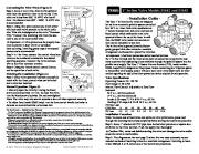
Connecting the Valve Wires (Figure 3) Step 1- Route a multi-wire, direct-burial sprinkler cable from the sprinkler timer to the valves. If the cable run is less than 800′, 18 AWG wire is sufficient. For distance from 800′ 2000′, 14 AWG wire is recommended. Step 2- Using wire splice connectors, attach either wire from each valve solenoid to the white cable wire. This wire is designated as the valve “Common Wire.
Lawn Sprinkler User Manual Free Download. Irrigation Free Instruction Manual Download PDF.
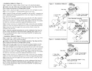
” Connect the remaining wire from the solenoid to one of the color-coded wires. Figure 3 Grease Cap Timer Connection 1 ” In-line Valve Models 53682 and 53683 – Installation Guide The Toro 1 ” in-line electric valves are designed for use in an automatic sprinkler system controlled by a 24 V a.c. timer. Both valve models feature 1 ” female-threaded inlet and outlet and manual bleed control which enables the valve to be operated without the use of the timer. In addition, the 53682 valve model features manual flow control adjustable to zero flow. The in-line valve is generally installed below 53683 grade, grouped with other valves in a manifold arrangement and housed in a protective valve box. 53682 Important: A backflow prevention device installed between the 1 ” in-line valve(s) and the water source point of connection is required in most areas to prevent back-siphoning of contaminants through the sprinkler system into the potable water supply. The Toro 1 ” Pressure Vacuum Breaker (PVB), model number 53300, is specifically designed for this purpose. Before connecting your irrigation system to the potable water supply, consult with your local water utility department for information regarding the type of backflow prevention device required for safe operation. Common Wire Important: All wire splices must be properly insulated to prevent a short circuit or corrosion Figure 4 from occurring. Installing grease caps or waterproof connectors is recommended. Step 3- At the timer, connect the control wires from valves to the numbered terminals in the desired operating sequence. Connect the valve common wire to the valve common terminal. Step 4- Using the timer’s manual control feature, test the operation of each valve. Finishing the Installation (Figure 4) Step 1- Once valve operation has been successfully tested with the timer, control wires can be buried and a valve box installed. Figure 5 Flow Control Handle Bleed Screw Valve Specifications: Operating Pressure: 20150 PSI Flow Range: 545 GPM Manual Flow Control: Adjustable to Zero Flow Solenoid: 24 V a.c., 60 Hz (nominal) 19 V a.c., 60 Hz (minimum) Inrush: 0.30 amps, 7.2 VA @ 24 V a.c., 60 Hz Holding: 0.20 amps, 4.8 VA @ 24 V a.c., 60 Hz Friction Loss: GPM Flow PSI Loss Manual Operation (Figure 5) · Manually open the valve by turning the bleed screw counterclockwise 1/2 turn. To close the valve, turn the bleed screw clockwise. Do not over-tighten! Note: The valve may take several seconds to shut off when operated manually. · To adjust flow, (model 53682 only) turn the flow control handle clockwise to decrease or counterclockwise to increase flow.


 Toro Owners Manual - 1 of 2
 Toro Owners Manual - 2 of 2