From inside (document excerpt):
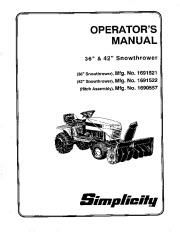
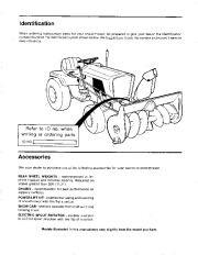
OPERATOR’S MANUAL 36 ” & 42 ” Snowthrower Mfg. No. 1691521 (42 ” Snowthrower), Mfg. No. 1691522 (Hitch Assembly), Mfg. No. 1690557 (36 ” Snowthrower), SilDpliDilg Identification When ordering replacement parts for your snowthrower, be prepared to give your dealer the identification number found on the identification plate shown below. We suggest you locate the number and record it here for easy reference. Refer to 10 no. when writing or ordering parts. ID NO.I _ Accessories See your dealer to purchase any of the following accessories for your tractor or snowthrower.
Snow Blower and Snow Thrower User Manual Free Download. Snow Removal Operator’s Manual. Free Manual Download PDF.
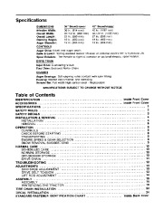
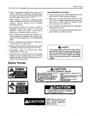
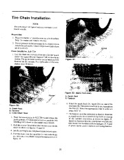
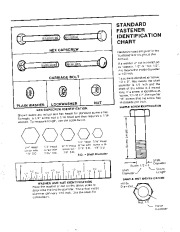
REAR WHEEL WEIGHTS – recommended to improve traction and increase stability. Required on slopes greater than 20% (11.3°). CHAINS – recommended for best performance on slippery surfaces. POWER LIFT KIT – enables the raising and lowering of snowthrower with the flip a switch. SNOW CAB – shelters operator from cold wind and blowing snow. ELECTRIC SPOUT ROTATOR – enables operator to control spout direction with the flip of a switch. Models illustrated in this manual may vary slightly from the model you have. Specifications DIMENSIONS Effective Width: Overall Width: Overall Length: Opening Height: Auger Diameter: CONTROLS Auger Drive: V-belt and auger chain. Raise & Lower: Spring assisted tractor lift lever or optional electric lift or hydraulic lift. Spout Rotation: Tee Handle to right of operator or optional electric spout rotator. DRIVE TRAIN Input Drive: Cushioning V-belt Final Drive: Enclosed Roller Chain CHASSIS Auger Bearings: Self-aligning roller contact with lube fitting Housing: Welded steel channel and stamping Scraper Bar: Full width high carbon steel – Replaceable SPECIFICATIONS SUBJECT TO CHANGE WITHOUT NOTICE 36 ” Snowthrower 36 In. (914 mm) 37-1/2 In. (953 mm) 27 In. (686 mm) 19 In. (483 mm) 12 In. (305 mm) 42 ” Snowthrower 42 In. (1067 mm) 43-1/2 In. (1105 mm) 27 In. (686 mm) 19 In. (483 mm) 12 In. (305 mm) Table of Contents IDENTIFICATION , ” . Inside Front Cover ACCESSORIES Inside Front Cover SPECIFICATIONS 1 SAFETY RULES 2 3 SAFETY DECALS INSTALLATION & REMOVAL 4 INSTALLATION 4 REMOVAL ‘ ” . 6 OPERATION 8 CONTROLS 8 CHECK BEFORE STARTING 8 TRANSPORTING 8 ENGINE SPEED & GEAR SELECTION 8 9 SNOW REMOVAL SUGGESTIONS NORMAL CARE ” 10 SCHEDULED CARE 10 NORMAL STORAGE 10 OFF-SEASON STORAGE 10 11 DRIVE CHAIN TROUBLESHOOTING 12 ADJUSTMENTS 13 13 SKID SHOE ADJUSTMENT DRIVE BELT TENSION 13 LIFT ROD ADJUSTMENT 14 ASSEMBLY , 15 ASSEMBLY 15 18 WINTERIZING THE TRACTOR TIRE CHAIN INSTALLATION 23 DECAL INSTALLATION ” 24 STANDARD FASTENER IDENTIFICATION CHART. . . Inside Back Cover Safety Rules Read these safety rules and follow them closely. Failure to obey these rules could result in loss of control of vehicle, severe personal injury to yourself or bystanders, or damage to property or equipment. The triangle in the text signifies important cautions or warnings which must be followed.
Wikipedia’s page for Simplicity Outdoor
Publisher: www.simplicitymfg.com


 Simplicity 1691521 1691522 1690557 36 42-Inch Snow Blower Owners Manual - Enlarge page 1 of 28
 2 of 28
 3 of 28
 4 of 28
 5 of 28
 6 of 28
 7 of 28
 8 of 28
 9 of 28
 10 of 28
 11 of 28
 12 of 28
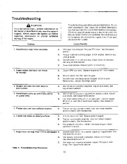 13 of 28
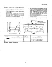 14 of 28
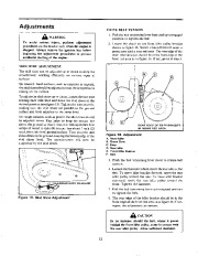 15 of 28
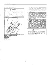 16 of 28
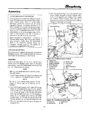 17 of 28
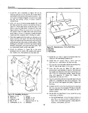 18 of 28
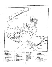 19 of 28
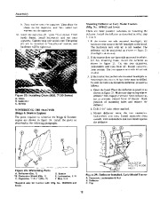 20 of 28
 21 of 28
 22 of 28
 23 of 28
 24 of 28
 25 of 28
 26 of 28
 27 of 28
 28 of 28