From inside (document excerpt):
ARTICLE No. 990221 · The 23 ” Rotary Snow Plow is shipped in one carton, with the handles and dis ch arge s pout removed. Clutch Rod Assembly To assemble the Snow Plow, follow the sequence of steps as outlined below: 1. Fasten the right and left handles to the mounting brackets as shown in Figure 1. Use hex capscrews, flat washers, lockwashers, and hex nuts and tighten securely in place. Transmission Shift Rod 5. Fig. 3 Applya coating of light oil to the neck of the discharge s pout mounting collar, and ins tall the spout in place on the rotor housing as shown in Figure 4.
Snow Blower and Snow Thrower User Manual Free Download. Snow Removal Operator’s Manual. Free Manual Download PDF.
The application of oil is necessary to prevent rust and to allow the spout to rotate freely. Clamp the “V ” belt around the spout as shown in ·Figure 4, and loop the belt around the adjusting pulley. Connect the lower end of the spout adjusting handle to the adjusting pulley as shown in Figure 4, using a hex capscrew and lock nut. Adjust the tension of the “V ” belt by turning the hex nut at point “A ” in Figure 4. Avoid excessive tension. Brackets Rotor Clutch Foot Pedal Fig. 1 “- 2. Attach the spout adjusting handle, shift rod, and clutch rod to the upper end of the handles as shown in Figure 2. Transmission Clutch Handle h T,an,mi,,!on Shift Rod Fig. 2 3. Connect the lower end of the shift rod to lever “A ” shown in Figure 3. Secure with a cotter pin. Connect the lower end of the clutch rod to the idler pulley using hex lock nut as shown in Figure 3. The lock nut should be tight enough to ve side play but loose enough to allow the bracket to pivot freely ·. , ·I I,, Spout Adjusting Rod Hex Caps crew & Lock Nut Fig. 4 4. «. 2 Belt Tension Belt tension for the rotor drive is regulated by the position of the set collar on the rotor clutch rod. Normally a clearance of 1/2 ” between the set collar and clutch rod clip will properly tension this belt. Check this adjustment when the rotor clutch is disengaged. Refer to Figure 5. ( To increase tension on the transmission drive belt, loosen the set screw in the collar and slide the collar toward the spring on the clutch rod. Retighten the set screw to lock the collar in place. Avoid excessive tension to prevent premature belt failure. Chain Tension The tension on the rotor drive chain may be increased by loosening the 2 lock nuts “A ” and turning the adjusting nuts “B ” to the desired position. Be sure to retighten the lock nuts “A ” after adjusting tension. Refer to Figure 7. ) :mission Idler Pulley Transmission Drive · ‘ “. – — -‘- 1Y ” ‘ – – Belt Belt Stops On the drive pulley side of the engine, 3 belt stops are mounted as shown in Figure 7. Engage the Rotor Clutch and Transmission Clutch and check clearance between belts and belt stops. The belt stops will be properly adjusted when 1/16 ” clearance is visible between the stops and the belts. To adjust, loosen the hex caps crews and reposition the stops to proper clearance. Retighten hex capscrews to hold stops in proper posilion. Refer to Figure 7. Lubrication The 23 ” Rotary Snow Plow is equipped with 4 grease fittings that require occasional lubrication with a general purpose automotive grease. The location of these fittings is shown in Figures I, 3, & 7. Fig. 5 To increase tension on the rotor drive belt, ·loosen the set screw in the collar and slide collar toward the spring on the rotor clutch rod. Retighten the set screw to lock collar in place. Avoid excessive tension to prevent premature belt failure. The bearings on the rotor shaft are a sealed type and do not require further lubrication. An occasional application of light motor 011 to the ends of the rotor shaft will aid in prolonging the life of the bearing seals. ‘r.r “‘ — Operation Before attempting to start the engine or to operate the snow plow, refer to the engine manufacturers owners manual for the proper fuel, oil, and procedure for starting the engine. The operation of the rotor is controlled by the rotor clutch. To engage the rotor clutch, raise the foot pedal shown in Figure 7. To disengage the clutch, depress the foot pedal. Bear in mind that the rotor will operate independently of the forward travel of the snow plow as long as the engine is running and the clutch is engaged. Exercise caution at all times, and never attempt to remove snow or ice from the rotor housing or discharge spout unless the engine is stopped and rotor clutch is disengaged. To stop the engine, move the throttle control knob all the way up to the shut-off position. The direction of travel of the snow plow is controlled by the position of the transmission shift lever. Refer to Figure 2. When shifting the transmission, always put the transmission clutch in disengaged position. To disengage the clutch, push the clutch leverforward. Refer to Figure 2. With the clutch disengaged, push forward on the transmission shift lever and the transmission will shift into forward position and snow plow will travel forward when the clutch is engaged. To reverse the snow plow, disengage the clutch and pull back on shift lever and transmis sion will shift into the reverse position. Neutral position of the shift lever is half way between forward and reverse and the lever will be held in this position by a detent lever on left side of the snow plow frame. 3 Belt tension for transmission drive belt is regulated by position ofthe set collar on the transmission clutch rod. Normally a clearance of 1/4 ” between the set collar and the clutch rod clip will properly tension the belt. Check this adjustment when the clutch is engaged. Refer to Figure 6.
Wikipedia’s page for Simplicity Outdoor
Publisher: www.simplicitymfg.com


 Simplicity 990221 23-Inch Snow Away Rotary Snow Blower Owners Manual - 1 of 12
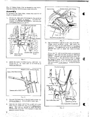 Simplicity 990221 23-Inch Snow Away Rotary Snow Blower Owners Manual - 2 of 12
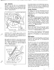 Simplicity 990221 23-Inch Snow Away Rotary Snow Blower Owners Manual - 3 of 12
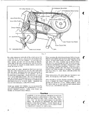 Simplicity 990221 23-Inch Snow Away Rotary Snow Blower Owners Manual - 4 of 12
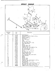 Simplicity 990221 23-Inch Snow Away Rotary Snow Blower Owners Manual - 5 of 12
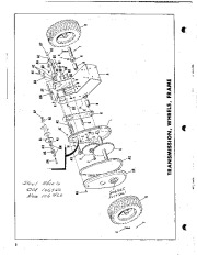 Simplicity 990221 23-Inch Snow Away Rotary Snow Blower Owners Manual - 6 of 12
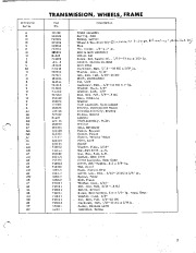 Simplicity 990221 23-Inch Snow Away Rotary Snow Blower Owners Manual - 7 of 12
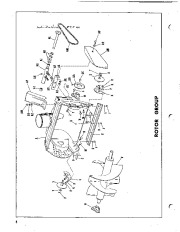 Simplicity 990221 23-Inch Snow Away Rotary Snow Blower Owners Manual - 8 of 12
 Simplicity 990221 23-Inch Snow Away Rotary Snow Blower Owners Manual - 9 of 12
 Simplicity 990221 23-Inch Snow Away Rotary Snow Blower Owners Manual - 10 of 12