From inside (document excerpt):
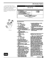
252 Series Valves Toro 252 Series plastic valves are extremely versatile, rugged commercial valves designed to provide a wide array of options for a variety of water conditions. Some models feature a fine-mesh, removable, stainless-steel filter screen for easy cleaning in dirty water conditions. Specifying Information 252 XX 0X Activation Type 06–1 ” (25mm) Electric 20–11/2 ” (40mm) Pin-Type Hydraulic 21–Normally Open Hydraulic 25–11/2 ” or 2 ” (40 or 50mm) Electric, Debris-Resistant 26–11/2 ” or 2 ” (40 or 50mm) Electric 27–11/2 ” or 2 ” (40 or 50mm) Pressure-Regulated Size 4–1 ” (25mm) 6–11/2 ” (40mm) 8–2 ” (50mm) For Example: When specifying a 11/2 ” (40mm) electric 252 Series Valve with pressure regulation, you would specify: 2522706 Specification s s 2 ” Electric s s Flow range: 1 ” — 5.0-40.0 GPM 1 1 /2 ” — 25.0-120.0 GPM 2 ” — 60.0-180.0 GPM Operating pressure: 20-150 PSI maximum Burst pressure safety rating: 750 PSI Body styles: Globe/Angle valve 1 1 “, 1 /2 ” or 2 ” female-threaded inlet and outlet BSP threads available Energy-efficient solenoid: 24 V a.c.
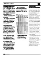
Inrush: 0.30 amps, 7.20 VA Holding: 0.20 amps, 4.80 VA Dimensions: 3 1 1 ” — 6 /4 ” H x 4 /2 ” W 1 3 1 /2 ” — 7 /4 ” H x 6 ” W 1 2 ” — 9 /2 ” H x 7 ” W Globe/Angle configuration Stainless-steel valve seat (11/2 ” & 2 ” models) to protect valve body Fabric-reinforced diaphragm (11/2 ” & 2 ” models) Rubber diaphragm (1 ” model) Manual flow control: adjustable to zero flow Manual bleed screw 24 ” lead wires (11/2 ” & 2 ” electric models) or 18 ” lead wires (1 ” electric model) for easy-access installation Self-cleaning, stainless-steel metering pin (electric models) Stainless-steel diaphragm differential spring for smooth, positive closing Single-piece rubber diaphragm for reliable, leak-free valve closing Precise pressure control (pressure-regulating models) Built-in Schrader-type valve (pressure-regulating models) s Removable, self-flushing, 120-mesh, stainless-steel filter screen (pressure-regulating and contamination-resistant models) Glass-filled Zytel cap for stability under pressure Engineering plastic and stainless-steel construction for exceptional durability Effluent flow-control knob available (Part No. 89-7855) Bidding Specifications The [1 ” / 11/2 ” / 2 “] 252 Series valve shall be of globe/angle configuration with a female-threaded inlet and outlet. The valve cap shall be constructed of glassfilled Zytel® for stability under pressure. The 11/2 ” and 2 ” valves shall have a stainless-steel valve seat for maximum durability. The diaphragm shall be of single-piece rubber construction to retain flexibility and provide maximum sealing throughout its area. The valve shall have a fabric-reinforced diaphragm on 11/2 ” and 2 ” models and a rubber diaphragm on 1 ” models. The diaphragm assembly shall form a solid-piece component. The valve shall have a forward-flow design and an external manual downstream bleed/flush. The valve shall have manual flow control with a hand-operated, rising-type flow-control stem with a control wheel/handle. For 1 ” models, friction loss at 40 GPM shall not exceed 7.5 PSI on electric, angle valves and 9.5 on electric, globe valves. For 11/2 ” models, friction loss at 120 GPM shall not (continued) SEPTEMBER 2000 252 Series Valves Bidding Specifications (cont.) exceed 11.0 PSI on hydraulic, angle valves; 13.5 PSI on hydraulic, globe valves; 9.0 PSI on electric, angle valves; and 15.0 PSI on electric, globe valves. For 2 ” models, friction loss at 180 GPM shall not exceed 6.0 PSI on hydraulic, angle valves; 11.0 PSI on hydraulic, globe valves; 7.0 PSI on electric, angle valves; and 11.0 PSI on electric, globe valves. The burst pressure safety rating shall be 750 PSI. An effluent flow-control knob and BSP threads shall be available options. Electric Models The valve shall be normally closed by internal water pressure. A [18 “/24 “] solenoid lead wire shall be attached to a removable 24 V a.c., 50/60 Hz solenoid with a waterproof coil. The valve shall have a self-cleaning, stainless-steel metering pin to protect bleed ports and purge contaminants. Pressure-Regulating Models The pressure regulator shall be a manually operated, locking type and shall regulate precisely over a 15-125 PSI range. The regulator shall maintain the set pressure within 3 PSI (with a minimum 10 PSI differential between inlet and outlet). The valve shall contain a built-in Schrader-type valve fitting for attaching a pressure gauge. The valve shall have a removable, self-flushing, 120-mesh, stainless-steel filter screen. Normally Open Hydraulic Models The normally open valve diaphragm chamber shall be isolated from the water supply and shall be operated by inline-filtered water from the controller. Quarter-inch control tubing shall enter the valve at the hydraulic adapter assembly. Pin-Type Hydraulic Models The valve shall have a normally closed diaphragm chamber. Supply water is metered from the inlet through the orifice plate. The controller selector valve shall block the discharge from the controller tube for normally closed operation. Contamination-Resistant Models The valve shall have a removable, self-flushing, 120-mesh, stainless-steel filter screen. The valve shall be developed, manufactured, qualified and released in the USA. The valve, model number __, shall be manufactured by The Toro Company, Irrigation Division, El Paso, Texas, USA. Recommended Installation Instructions In all installations, it is advantageous to mount valves in a valve box. Logically, if mounted in valve boxes, they can be found, accessed and maintained easily. Instructions should include the use of clean aggregate to fill the bottom of the box, and keeping valve box locations away from structures, potential 252 Friction Loss* hardscaping features (such as sidewalks) G For optimum performance when designing a system, calculate total friction loss to ensure used to reduce high available pressure sufficient downstream pressure. due to a change in elevation or where a 2. For optimum regulator performance, size lower lateral line pressure is required. regulating valves toward the higher of flow Electric control valve instructions ranges. should specify direct-burial wire, utilizing * Contamination-resistant valves are electric only.


 Toro Owners Manual - 1 of 2
 Toro Owners Manual - 2 of 2