From inside (document excerpt):
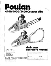
Read Rules for Safe Operation CarefulIy. Note Special I nstructions for Bow Saw Users. operator’s manual Record in the space provided below the model number and serial number of your saw. Model No. Serial No. _ chGinsaw BEAIRD-POULAN/WEED EATER Division Emerson Electric Co 5020 Flournoy-Lucas Road Shreveport, Louisiana 71109 Retain these numbers for future reference. TABLE OF CONTENTS Bar and Chain Installation : 3, 4 Chain Adjustment 3, 4 7 Bow Installation Operating Instructions 4, 5 Cutting Tips Bow Cutting Tips 7 Felling ” .
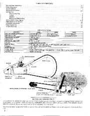
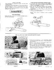
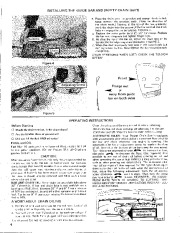
5 Bucking . 6 Pruning and Debranching . 6 Special Safety Center Spread 8, 9 , 10 Replacing Drum & Sprocket Carburetor Adjustment 11 ” 12 Chain Sharpening Trouble Shooting MODEL CU. IN. DISPLACEMENT SPARK PLUG SPARK PLUG GAP IGNITION MODULE AI R GAP OILER GUIDE BAR CHAIN BOW GUIDE FUEL MIX MUFFLER SPECIFICATIONS 5400 4400 4900 4.2 in 3 /69 cm 3 4.7 in 3 /77cm 3 5.2in 3 /85cm 3 Champion CJ·4 Champion CJ-8 Champion CJ-8 .023 to .027 ” Solid State .008 to .014 ” Adjustable Automatic Failure to do so will subject you to a liability for a fine. 2 SAFETY FEATURES HAND GUARD MOUNTING INSTRUCTIONS 1. Assemble the hand guard to the bend in the handlebar as shown. Be sure alignment pin on guard is inserted in hole in handlebar. Do not tighten the screws. 2. Make sure the hand guard is parallel to the handlebar. Alternately tighten each hand guard mounting screw maintaining an even gap between the hand guard and mounting cap. 3. Tighten the mounting screws until the hand guard and mounting cap are pulled together. Caution: Screws must be tightened evenly to prevent breakage. Your new chain saw is equipped with guard link safety chain to reduce kickback. A hand guard is provided to protect your hand from coming in contact with the cutting chain in the event your hand slips off the front handlebar or you lose control of the saw. Hand guards do not eliminate the possibility of injury as a result of kickback or loss of control. THIS SAW INTENDED FOR PROFESSIONAL USE ONLY. SPUR MOUNTING I I Position the Spur as shown over the holes and attach securely with the screws provided. I –. -. INSTALLING THE GUIDE BAR AND SAFETY CHAIN 1. Remove the bar mounting nuts. Using the scrench packed with your saw, loosen the nuts by turning counterclockwise. FIGURE 1. 2. Remove the bar clamp and outer guide bar plate. (Note position ofthe guide plates.) FIGURE 2. 3. Place “S ” clip over the mounting studs and flush to the inner bar plate. Now mount the slotted end of the guide bar over the bar mounting studs and “S ” clip and behind the clutch drum. Be sure to position the bar adjusting pin into the hole in the guide bar. FIGURE 3.


 Poulan Owners Manual - 1 of 13
 Poulan Owners Manual - 2 of 13
 Poulan Owners Manual - 3 of 13
 Poulan Owners Manual - 4 of 13
 Poulan Owners Manual - 5 of 13
 Poulan Owners Manual - 6 of 13
 Poulan Owners Manual - 7 of 13
 Poulan Owners Manual - 8 of 13
 Poulan Owners Manual - 9 of 13
 Poulan Owners Manual - 10 of 13