From inside (document excerpt):
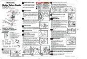
TP 1000-4518-03-LW-SN:QS_TroyBilt_REV7.qxd 11/5/2007 11:41 AM Page 1 2 Read the Operator’s Manual 8 Spout Rotator Brake Cable Connection Quick Setup Guide Two-Stage Snowthrower 1694986 10530L, 10.5 Snowthrower Auger Engage Control Chute Rotator Control Head Light Speed Selector Chute Deflector Control Traction Engage Control Easy Turn Lever · Locate the operator’s manual in the manual packet. Always read and follow the instructions in the operator’s manual. Proper care, performance tips, and safety information are located in this important document.
Snow Blower and Snow Thrower User Manual Free Download. Snow Removal Operator’s Manual. Free Manual Download PDF.
· “Right ” and “Left ” are from the Operating Position. Slide the spout rotator brake cable (E, Figure 9) between the dash and the handle cross bar as shown. Slide the rubber dust cover (D, Figure 10) off of plastic fitting (B). Place “Z ” bend of cable (C) into hole (G) of brake lever assembly (E) Pull plastic fitting (B) behind bracket (E). Slide chute rotator cable (A) between slot in bracket (E) and push forward to lock in place. Slide the rubber dust cover (F) over the plastic fitting (B). Raise The Handles D E C E D B A Fuel Cap Oil Dip Stick · Cut four orange zip ties (E, Figure 3) that secure control cables to handle assembly (C). Be careful not to cut or damage the control cables. · Loosen nuts (B) in upper holes with a 1/2 ” wrench. Rotate upper handle assembly (A) up. Locate two carriage bolts and two 5/16 nuts in parts bag (B, Figure 1). Slide carriage bolts (D) and nuts (B) into lower holes. Tighten all hardware with a 1/2 ” wrench or deep socket. Figure 10 B D A 9 Remove Snowthrower From Crate A Clean-Out Tool 4 Chute Deflector Cable Drift Cutter Install Chute Rotator Control Handle · Cut the two zip ties from between wheels and the wood pallet. · Remove screws (A, Figure 11) from both skid shoes (B). · Roll snowthrower off crate. Drift Cutter · Install thin jam nut (B, Figure 4) onto chute rotator rod (C). Install chute rotator control handle (A) onto chute rotator rod (C) turing at least 10 full rotations. Figure 3 · Align chute rotator control handle so it is facing forward and use a 9/16 ” wrench to tighten jam nut (B) against chute rotator control handle (A). · Slide chute rotator control handle to the right hand side. A 10 Add Oil and Fuel B Figure 1 Skid Shoe For Assembly You Will Need: · Utility knife · Tin Snips or Banding Cutter · Unleaded fuel · Pliers · Tire Pressure Gauge · 1/2 ” Combination Wrench or 1/2 ” Deep Socket & Ratchet.
Wikipedia’s page for Simplicity Outdoor
Publisher: www.simplicitymfg.com


 Simplicity 10.5 1694986 10530L Snow Blower Quick Setup Guide Manual - 1