From inside (document excerpt):
Commercial Products Automated Control Electronics (ACETM) System Operation and Diagnostics PART NO. 98962SL This page is intentionally blank. Table of Contents Introduction 1 Controller Operation and Protection 2 ClipAce 4 New Machine Set-up . 7 Diagnostic Tools 8 Controllers and Functions . 10 Diagnostic Lamps 11 Quick Reference Guides . 12 This page is intentionally blank. Introduction ACE is an acronym for Automated Control Electronics.
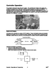
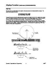
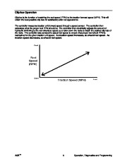
The “ACE System ” is a machine control system which is currently used on the Groundsmaster® 580-D, Reelmaster® 5000/6000 series fairway mowers and Greensmaster® 3200 (gasoline only). All of these machines operate under the same concepts and TM utilize common diagnostic procedures. The ACE System is also used to control the TurfDefender TM hydraulic leak detection system and Sonic Boom accessory for spray systems. The ACE System was developed for several reasons: · Ease of operation and safety. · Reduces mechanical linkage requirements (and adjustments). · Reduces electrical wiring and components. · Reliability. TM · Allows ClipAce function on some fairway mowers (matches reel speed to traction speed). · Common manufacturing and servicing capabilities. The heart of the ACE system is an electronic control unit (ECU). This provides us with several advantages: · Simplified diagnostic procedures. · Software upgrades. · Operational characteristics can be customized easily. · Expandable system. The “ACE System ” includes two sub-systems: · Electrical system. · Hydraulic system. The simplest explanation of the ACE system is that it utilizes an electrical system to control and activate the hydraulic system of a machine. This is extremely important to understand the interaction of these two systems because an ELECTRICAL PROBLEM CAN CAUSE A HYDRAULIC CONTROL VALVE TO MALFUNCTION, but a HYDRAULIC PROBLEM CAN NOT CAUSE AN ELECTRICAL MALFUNCTION. If something goes wrong on the machine, the first step in diagnosis is to determine if the problem is electrical or hydraulic. Because the controller provides us with enhanced diagnostic capabilities, electrical system tests can be performed easily and quickly. Note: If a machine equipped with ACE malfunctions, always check the electrical system first, before looking for possible hydraulic problems. Follow proper troubleshooting procedures. Talk to the operator. By asking the correct questions, the operator may actually tell you what is wrong. It could be as simple as not understanding how the system operates (example: Reel Control lamp illuminates while mowing). Some questions to ask the operator: · Exactly what is happening? · Was (or is) the Diagnostic Lamp flashing? NO = First use the Diagnostic ACE Display tool to check INPUTS, then perform hydraulic tests. YES =Use Diagnostic ACE Display tool to check OUTPUTS. · Is the problem repeatable? or is it intermittent? Note: The controller can store output fault information which can be retrieved with the Diagnostic ACE Display tool. This can be very helpful when diagnosing intermittent problems. This feature requires a controller software upgrade on machines built prior to the 1997 model year (S/N before 70001). TM ACE TM 1 Operation, Diagnostics and Programming Controller Operation The controller (ECU) is the heart of the ACE system. The controller is the “brains ” of the system and contains the programming (or instructions) needed to properly operate the machine it is installed in. All controllers currently in use are the same. What makes the controller a Groundsmaster 580-D or a Reelmaster 5300-D is the software that is programmed into the controller. Initial machine programming is performed at the factory when the controller is installed into a machine, but can also be performed by an authorized Toro Distributor if necessary. Inputs and Outputs Connected to the controller are a series of INPUT switches. These on/off switch devices send electrical signals to the controller when an operator has made a request. The controller will then process the input information, decide what to do, and turn on the correct OUTPUT device to meet the operator’s requests. Important information to remember: · Inputs are usually switches (on/off devices). · Outputs are usually solenoids (load devices). Note: Not all outputs are solenoids. Diagnostic Lamps are also outputs. ECU Input Output Operation, Diagnostics and Programming 2 ACE TM Controller Protection An output solenoid, which is activated by the controller, can have a large current draw if it fails in a “shorted ” condition. If it fails “open “, it will not draw any current. These two conditions are known as faults. If either one of these faults occur, the controller will automatically shut off the output to prevent damage. The fault will register as a flashing Diagnostic Lamp and will be saved in the controller memory. Note: The controller memory cannot tell you what kind of fault occurred (short or open circuit), but it will tell you what output solenoid (or related wiring) has failed. The input switches only send on/off signals (switch state change) to the controller. A faulty input will not be saved in the controller memory. Important information to remember: · A defective input switch or wiring will NOT register as a fault in the controller. · The controller will only inform the operator of output faults. · An output fault can be retrieved from controller. ACE TM 3 Operation, Diagnostics and Programming ClipAce Function (Reelmaster 5100/5300/6500/6700) Clip Rate Clip rate is the numerical distance the traction unit travels between reel blade/bedknife contacts. The actual mathematical formula is: Ground Speed (in/min) x MPH No. of Reel Blade x Reel RPM Research has shown that the desired clip rate is equal to the Height-of Cut (H.O.C.) setting of the cutting unit. If the cutting unit is set at 1/2 inch (13 mm) H.O.C., then for best results, every 1/2 inch (13 mm) of forward movement a reel blade should cut grass. This produces the best after-cut appearance. On a machine with a manually set reel speed this would mean that there is a limited variance of traction speed in which the desired clip rate is actually achieved. If traction speed is too fast, a “choppy ” after-cut appearance may be visible. If traction speed is too slow, the reels may fan the grass away, which may result in a “fuzzy ” after-cut appearance. Operation, Diagnostics and Programming 4 ACE TM ClipAce Operation ClipAce is the function of matching the reel speed (RPM) to the traction forward speed (MPH). This will obtain the best possible clip rate for satisfactory after-cut appearance. The controller measures traction unit forward speed through a speed sensor. The controller then calculates what the proper reel RPM should be. The controller then electrically adjusts the amount of hydraulic oil flowing to the reel circuits to speed up or slow down the reels to match the desired clip rate of the reels. The controller also senses the actual reel speed to ensure that proper reel circuit RPM is maintained for the given traction unit speed. As traction speed increases, so should reel speed. As traction speed decreases, so should reel speed. ACE TM 5 Operation, Diagnostics and Programming Controller (ECU) Information for ClipAce Operation There are several cutting unit blade configurations available for the Reelmaster 5000/6000 series mowers, depending on the customers desired H.O.C. range. In order for ClipAce control to function properly, the controller (ECU) needs two important pieces of information: Number of blades on the installed cutting units. The number of blades is critical information needed to determine the desired reel RPM vs. MPH to match clip rate. This information is programmed into the controller during set-up of the machine at the Distributor. What the Height of Cut (H.O.C.) setting is of the installed cutting units. This information is critical for the controller to be able to match the clip rate (reel RPM) to the traction forward speed. This information is provided to the controller electrically by rotating the H.O.C. Selection Knob (located inside the operators control console) to the desired setting. Each machine is equipped with a H.O.C. selection chart located under the Seat platform. Reel Control Lamp Operation (ClipAce Function)
Wikipedia’s page for Toro Company
Company Web Site: www.toro.com


 Toro Commercial Products Automated Control Electronics ACETM System Operation Diagnostics 98962SL - 1 of 28
 Toro Commercial Products Automated Control Electronics ACETM System Operation Diagnostics 98962SL - 2 of 28
 Toro Commercial Products Automated Control Electronics ACETM System Operation Diagnostics 98962SL - 3 of 28
 Toro Commercial Products Automated Control Electronics ACETM System Operation Diagnostics 98962SL - 4 of 28
 Toro Commercial Products Automated Control Electronics ACETM System Operation Diagnostics 98962SL - 5 of 28
 Toro Commercial Products Automated Control Electronics ACETM System Operation Diagnostics 98962SL - 6 of 28
 Toro Commercial Products Automated Control Electronics ACETM System Operation Diagnostics 98962SL - 7 of 28
 Toro Commercial Products Automated Control Electronics ACETM System Operation Diagnostics 98962SL - 8 of 28
 Toro Commercial Products Automated Control Electronics ACETM System Operation Diagnostics 98962SL - 9 of 28
 Toro Commercial Products Automated Control Electronics ACETM System Operation Diagnostics 98962SL - 10 of 28