From inside (document excerpt):
DDCWPTM Series Waterproof Battery Controller INSTALLATION AND OPERATING INSTRUCTIONS Thank you for choosing the Toro DDCWP Waterproof Battery Controller. The DDCWP incorporates the latest programming technology in an easy-to-use, “digital dial ” display. The following instructions will help you get started. As you follow the simple steps, please pay attention to the important NOTES, which will give you helpful hints and programming advice to maximize the feature capability of the DDCWP. TABLE OF CONTENTS Controller Specifications Page 3 Installation Instructions .
Lawn Mowing User Manual Free Download. Power Lawn Mower Free Instruction Manual Download PDF.
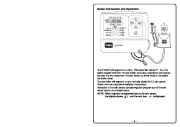
Page 3-4 Sensor Connection and Operation . Page 5 Programming Page 6 – SET TIME/DAY Page 6 – RUN TIME . Page 6 – WATER DAYS . Page 7 – START TIMES . Page 7 – WATER BUDGET (Season Adjust) . Page 8 – MANUAL Page 8 – MANUAL PROGRAMS . Page 9 – SYSTEM OFF . Page 9 – AUTO-RUN Page 10 Automatic Voltage Detection . Page 11 About the DDCWP Memory . Page 11 Wire Run . Page 11 Custom Watering Plan . Page 12 -2- Controller Specifications: The DDCWP will run one master valve and one station valve simultaneously. The DDCWP is a DC controller. This means it ONLY runs DC latching solenoids. It will not run AC solenoids. It has been fully tested using Toro DC Latching Solenoids. If you intend to use other brands, test them before making an installation. As DC latching solenoids are more susceptible to debris than AC solenoids, Toro recommends that a filter and master valve be installed in the system. The DDCWP is tested to be operational under 2 meters of water and is marked IP68. It is important to completely dry the controller before opening the battery compartment. It is also important to make waterproof connections for the longevity of the system components. The DDCWP is supplied with 3M waterproof connectors for this purpose. If more connectors are required, Toro recommends 3M DBY type connectors as these are readily available in most markets. Connect all field wiring before applying battery power to the controller. This will insure that all connected DC solenoids are properly calibrated for operation. Installation Instructions: DDCWP Controller Level and mount controller mounting bracket to a solid surface. If mounting in a valve box, it is suggested to mount the bracket under the lid and leave sufficient wire so the lid can be removed to access the controller. Next connect the solenoid wires to the controller. The controller drives Toro latching solenoids. It is essential for proper operation that the wire colors between the solenoid and the controller be matched. The red controller station wire is connected to the red solenoid wire and the black controller common wire is attached to the black solenoid wire. It is also essential that a waterproof wire connection be made. The DDCWP is shipped with waterproof connectors for this purpose. These can be used for wire sizes 19 to 26 AWG. (0.9 metric is the largest size wire these accept) (continued on next page) -3- Installation Instructions: DDCWP Controller (continued) RESET button DIGITAL DIAL Advancement button WATERPROOF CAP Attach 2 9VDC alkaline batteries black common wire orange master valve wire red station wires DO NOT CUT IF NOT CONNECTING TO A RAIN SENSOR yellow rain sensor wire.
Wikipedia’s page for Toro Company
Company Web Site: www.toro.com


 Toro DDCWP Owners Manual - Enlarge page 1 of 12
 2 of 12
 3 of 12
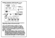 4 of 12
 5 of 12
 6 of 12
 7 of 12
 8 of 12
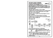 9 of 12
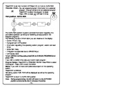 10 of 12
 11 of 12
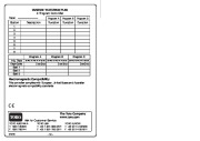 12 of 12