From inside (document excerpt):
Electrical Systems Principles, Circuits, Schematics, Test Equipment, and Components PART NO. 09170SL This page is intentionally blank. Electrical Systems Table of Contents 1 Introduction 2 Electrical Principles . 4 Basic Circuits . 5 Schematics 8 Testing Tools . 10 Circuit Testing 15 Components 19 Toro University Technical Training 2 Electrical Systems Introduction Electricity plays an important role in modern turf equipment Electricity plays an important role in modern turf equipment.
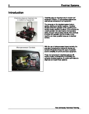
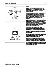
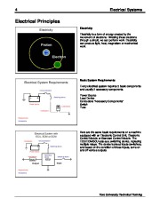
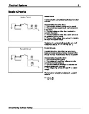
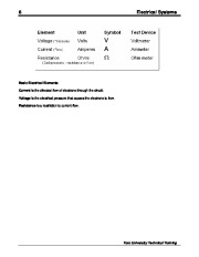
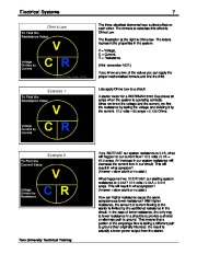
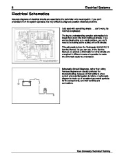
Modern 12 volt electrical systems are used almost exclusively in turf equipment. The demands on the electrical system include: starting, lighting and ignition systems. Electrical circuits control the operation of the machines and monitor certain machine functions. They enhance the overall operation and also improve the operators safety, through various safety circuits. New methods to control the operation and the function of the machine are made possible because of electrical devices. Microprocessor Controls With the use of microprocessor based controls, the potential of electrical and electronic circuits and controls will greatly change the ease of operation and the reliability of current and future equipment. These new advances in electrical systems will require a better understanding of electricity and complete electrical systems, to enable technicians to diagnose and repair these systems. Toro University Technical Training Electrical Systems Safety Safety While the risk of electrical shock is relatively low when working on a 12 volt electrical system, care must be taking when working on equipment electrical systems. Fumes from battery electrolyte are flammable. Keep all sparks and fires away from the battery. When charging the battery, explosive fumes are produced more rapidly. Be sure the room or area where batteries are being recharged is well ventilated. 3 Battery acid is harmful on contact with the skin or most materials. If acid contacts the skin, rinse the affected area with running water for 10 to 15 minutes. If acid contacts the eyes, force the eyelids open and flush the eyes with running water for 10 to 15 minutes. Then see a doctor at once. Safety To avoid injury from sparks or short circuit, Disconnect the negative battery ground cable when working on any part of the electrical system. Remove all Jewelry and watches when working on live circuits. Injury can result from high temperature caused when jewelry, rings or watches come in contact with powered circuits and ground circuits. When removing batteries always disconnect the negative battery cable first. When reconnecting the battery wait until last to connect the negative cable. Do not lay tools or parts across the battery, the metal parts or tools can short across the battery posts and a fire or explosion can result. Toro University Technical Training 4 Electrical Systems Electrical Principles Electricity Electricity Electricity is a form of energy created by the movement of electrons. Directing these electrons through a circuit, we can perform work. Electricity can produce light, heat, magnetism or mechanical work. Electrical System Requirements Circuit protection Basic System Requirements Every electrical system requires 3 basic components and usually 2 accessory components. Switching device Power source Load device Conductors Power Source Load Device Conductors “Accessory Components ” Switch Fuse Requirements Accessories Electrical System with ECU, ECM or SCM Conductors Circuit protection Switching device Power source Load device Switching device Here are the same basic requirements on a machine equipped with an Electronic Control Unit, Electronic Control Module or Standard Control Module. The ECU/ECM/SCU acts as a switching device, replacing multiple relays. The device looks at inputs (switches), and based on the condition of those inputs, turns on and off various outputs. Switching device ECU Output Requirements Accessories Input Toro University Technical Training Electrical Systems 5 Basic Circuits Series Circuit Series Circuit A series circuit is a circuit that may include more than one load. Characteristics of a series circuit: 1: The current is constant through out the circuit. 2: The current must pass through each component in the circuit. 3: The total resistance of the circuit controls the current in the circuit. 4: The total resistance of the circuit is the sum of all the resistance’s in the circuit. 5: The sum of the voltage drops across the resistors will equal the applied voltage. Resistance in a series circuit equals the sum of all resistance’s (that is, R = R1+R2+R3+ etc .) Parallel Circuit Parallel Circuits A parallel circuit is a circuit that has two or more loads connected so that current can divide and flow through the load. Most electrical circuits are parallel. Characteristics of a parallel circuit: 1: The current has many paths. 2: The resistance in each load will determine the current flow for that resistance. 3: The total resistance will always be less than the smallest resistance in the circuit. 4: The voltage drop across all loads will be battery voltage. The formula for calculating resistance in a parallel circuit is: R = R1 x R2 R1 + R2 Toro University Technical Training 6 Electrical Systems Basic Electrical Elements Current is the directed flow of electrons through the circuit. Voltage is the electrical pressure that causes the electrons to flow. Resistance is a restriction to current flow. Toro University Technical Training Electrical Systems Ohm’s Law 7 The three electrical elements have a direct effect on each other. The formula to calculate this effect is Ohms Law. The illustration at the right is Ohms law. The letters represent the properties in the system. V = Voltage, C = Current, R = Resistance. (Hint: remember VCR.) If you know any two of the values you can apply the proper mathematical formula and find the third. Example 1 Lets apply Ohms Law to a circuit A starter motor for a WORKMAN 3200 Gas draws 90 amps when the system is operating correctly. Since we know the voltage and the current, we find the resistance by taking the voltage and dividing it by the current. 12.5 volts ÷ 90 amps = 0.135 Ohms Example 2 If we INCREASE our system resistance to 0.2A, what will happen to our current flow? 12.5 volts / 0.2A = 62.5 amps. An increase in our system resistance will decrease the current flow in our circuit. This will result in what symptom? (Answer = slow crank or no start.) What happens if we DECREASE our starting system resistance to 0.04A? 12.5 volts / 0.04A = 312.5 amps. This will result in what symptom? (Answer = slow crank or no start.) How can higher resistance cause the same symptoms as lower resistance? With higher resistance, the amount of current flowing to the starter is limited by the additional resistance in the circuit. In the case of lower resistance, the only way to lower resistance in a circuit is to provide a shorter or alternate path to ground. That means that a portion of the amperage flow is taking a different path to ground than originally intended. the result is actually a lower power output from the starter. Toro University Technical Training 8 Electrical Systems Electrical Schematics Accurate diagrams of electrical circuits are essential to the technician who must repair it. If you don’t understand how the system operates, it is very difficult to diagnose possible electrical problems. Let’s start with something simple. don’t worry, its not that complicated. The key to understanding complex schematics is to break them down into their individual circuits. If you are troubleshooting a no crank problem, you don’t need to be looking at the cutting unit or lift circuits. This schematic is from the Reelmaster 6500/6700-D Service Manual. As you can see, in the Service Manual, we provide a information on what circuits are energized in different modes of operation to make the schematic easier to understand. Schematic Circuit Diagrams, rather than wiring harness diagrams are usually preferred for troubleshooting, because of their ability to show current and potential system functions. A schematic diagram is made up of consistent geometric symbols for the components, and their controls and connections. Toro University Technical Training Electrical Systems Let’s identify some of the symbols we use in Toro electrical schematics.
Wikipedia’s page for Toro Company
Company Web Site: www.toro.com


 Toro Electrical Systems Principles Circuits Schematics Test Equipment Components 09170SL - 1 of 36
 Toro Electrical Systems Principles Circuits Schematics Test Equipment Components 09170SL - 2 of 36
 Toro Electrical Systems Principles Circuits Schematics Test Equipment Components 09170SL - 3 of 36
 Toro Electrical Systems Principles Circuits Schematics Test Equipment Components 09170SL - 4 of 36
 Toro Electrical Systems Principles Circuits Schematics Test Equipment Components 09170SL - 5 of 36
 Toro Electrical Systems Principles Circuits Schematics Test Equipment Components 09170SL - 6 of 36
 Toro Electrical Systems Principles Circuits Schematics Test Equipment Components 09170SL - 7 of 36
 Toro Electrical Systems Principles Circuits Schematics Test Equipment Components 09170SL - 8 of 36
 Toro Electrical Systems Principles Circuits Schematics Test Equipment Components 09170SL - 9 of 36
 Toro Electrical Systems Principles Circuits Schematics Test Equipment Components 09170SL - 10 of 36